Home » Classification of Motion

Classification of Motion
Random Motion
Such motion is non-predictable and occurs from the manual handling of a hose assembly. Care must be taken to prevent over-bending of the hose to avoid external abrasion of the wire braid. An armor covering of interlocked hose provides protection against these abuses.
Axial Motion
This type of motion occurs when there is extension or compression of the hose along its longitudinal axis. This class of motion is restricted to unbraided corrugated hose only and is accommodated by traveling loops or bellows specifically designed for this purpose.
Angular Motion
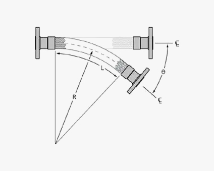
This type of motion occurs when one end of a hose assembly is deflected in a simple bend with the ends not remaining parallel.
To find the live hose length:
- L = πRØ/180 + 2(s)
- L = Live Hose Length (inches)
- π = 3.1416
- R = Minimum Centerline Bend Radius — Dynamic (in.)
- Ø = Angular Deflection (degrees)
- S = Outside Diameter of Hose
Offset Motion
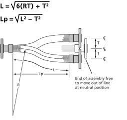
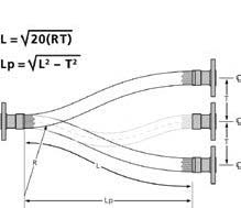
Offset motion occurs when one end of the hose assembly is deflected in a plane perpendicular to the longitudinal axis with the ends remaining parallel. This movement can be due to a one-time (static) bend or movement which repeatedly occurs slowly over time (such as thermal expansion).
- The appropriate formula to use to calculate Live Hose Length depends on the condition of the moving end.
- When the offset motion occurs to both sides of the hose centerline, use total travel in the formula; ie 2 x “T”.
- The offset distance “T” for constant flexing should never exceed 25 percent of the centerline bend radius “R”.
- If the difference between “L” and “Lp” is significant, exercise care at installation to avoid stress on hose and braid at the maximum offset distance.
- L = Live Hose Length (inches)
- Lp = Projected Live Hose Length (inches)
- R = Minimum Centerline Bend Radius — Dynamic (in.)
- T = Offset Motion to One Side of Centerline (inches)

Traveling Loops
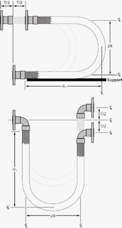
In a piping system where axial movement must be accommodated or where the magnitude of the motion is in excess of the limits of an offset movement, the traveling loop configuration offers an ideal solution. In traveling loops, the center line of a hose assembly is bent in a circular arc. Traveling loops accommodate movement in one of two ways. A constant radius traveling loop accommodates motion by varying the length of the arms of the assembly while the radius remains constant. A variable radius traveling loop accommodates motion by varying the bend radius of the hose assembly. Both types of traveling loops can be installed to absorb either horizontal or vertical movement. The constant radius traveling loop provides greater movement while the variable radius traveling loop requires less installation space.
- L = Live Hose Length (inches)
- R = Minimum Center Line Bend Radius for Constant Flexing (inches)
- T = Total Travel (inches)
- H = Hang Length of the Loop (inches)
Constant Radius Traveling Loop – Class A
- L= 4R + T/2
- H1 = 1.43R + T/2


